1.0 Introduction to Thermoelectric Cooling
1.1 A thermoelectric (TE) cooler, sometimes called a thermoelectric module or Peltier cooler, is a semiconductor-based electronic component that functions as a small heat pump. By applying a low voltage DC power source to a TE module, heat will be moved through the module from one side to the other. One module face, therefore, will be cooled while the opposite face simultaneously is heated. It is important to note that this phenomenon may be reversed whereby a change in the polarity (plus and minus) of the applied DC voltage will cause heat to be moved in the opposite direction. Consequently, a thermoelectric module may be used for both heating and cooling thereby making it highly suitable for precise temperature control applications.
1.1.1 To provide the new user with a general idea of a thermoelectric cooler’s capabilities, it might be helpful to offer this example. If a typical single-stage thermoelectric module was placed on a heat sink that was maintained at room temperature and the module was then connected to a suitable battery or other DC power source, the “cold” side of the module would cool down to approximately -40°C. At this point, the module would be pumping almost no heat and would have reached its maximum rated “DeltaT (DT).” If heat was gradually added to the module’s cold side, the cold side temperature would increase progressively until it eventually equaled the heat sink temperature. At this point the TE cooler would have attained its maximum rated “heat pumping capacity” (Qmax).
1.2 Both thermoelectric coolers and mechanical refrigerators are governed by the same fundamental laws of thermodynamics and both refrigeration systems, although considerably different in form, function in accordance with the same principles.
In a mechanical refrigeration unit, a compressor raises the pressure of a liquid and circulates the refrigerant through the system. In the evaporator or “freezer” area the refrigerant boils and, in the process of changing to a vapor, the refrigerant absorbs heat causing the freezer to become cold. The heat absorbed in the freezer area is moved to the condenser where it is transferred to the environment from the condensing refrigerant. In a thermoelectric cooling system, a doped semiconductor material essentially takes the place of the liquid refrigerant, the condenser is replaced by a finned heat sink, and the compressor is replaced by a DC power source. The application of DC power to the thermoelectric module causes electrons to move through the semiconductor material. At the cold end (or “freezer side”) of the semiconductor material, heat is absorbed by the electron movement, moved through the material, and expelled at the hot end. Since the hot end of the material is physically attached to a heat sink, the heat is passed from the material to the heat sink and then, in turn, transferred to the environment.
1.3 The physical principles upon which modern thermoelectric coolers are based actually date back to the early 1800’s, although commercial TE modules were not available until almost 1960. The first important discovery relating to thermoelectricity occurred in 1821 when a German scientist, Thomas Seebeck, found that an electric current would flow continuously in a closed circuit made up of two dissimilar metals provided that the junctions of the metals were maintained at two different temperatures. Seebeck did not actually comprehend the scientific basis for his discovery, however, and falsely assumed that flowing heat produced the same effect as flowing electric current. In 1834, a French watchmaker and part time physicist, Jean Peltier, while investigating the “Seebeck Effect,” found that there was an opposite phenomenon whereby thermal energy could be absorbed at one dissimilar metal junction and discharged at the other junction when an electric current flowed within the closed circuit. Twenty years later, William Thomson (eventually known as Lord Kelvin) issued a comprehensive explanation of the Seebeck and Peltier Effects and described their interrelationship. At the time, however, these phenomena were still considered to be mere laboratory curiosities and were without practical application.
In the 1930’s Russian scientists began studying some of the earlier thermoelectric work in an effort to construct power generators for use at remote locations throughout the country. This Russian interest in thermoelectricity eventually caught the attention of the rest of the world and inspired the development of practical thermoelectric modules. Today’s thermoelectric coolers make use of modern semiconductor technology whereby doped semiconductor material takes the place of dissimilar metals used in early thermoelectric experiments.
1.4 The Seebeck, Peltier, and Thomson Effects, together with several other phenomena, form the basis of functional thermoelectric modules. Without going into too much detail, we will examine some of these fundamental thermoelectric effects.
1.4.1 SEEBECK EFFECT: To illustrate the Seebeck Effect let us look at a simple thermocouple circuit as shown in Figure (1.1). The thermocouple conductors are two dissimilar metals denoted as Material x and Material y.
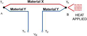
In a typical temperature measurement application, thermocouple A is used as a “reference” and is maintained at a relatively cool temperature of Tc. Thermocouple B is used to measure the temperature of interest (Th) which, in this example, is higher than temperature Tc. With heat applied to thermocouple B, a voltage will appear across terminals Tl and T2. This voltage (Vo), known as the Seebeck emf, can be expressed as:
Vo = axy x (Th – Tc)
where:
Vo = the output voltage in volts
axy = the differential Seebeck coefficient between the two materials, x and y, in volts/°K
Th and Tc = the hot and cold thermocouple temperatures, respectively, in °K
1.4.2 PELTIER EFFECT: If we modify our thermocouple circuit to obtain the configuration shown in Figure (1.2), it will be possible to observe an opposite phenomenon known as the Peltier Effect.
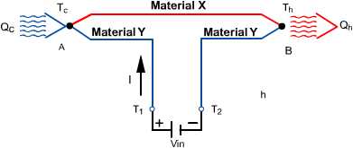
If a voltage (Vin) is applied to terminals Tl and T2 an electrical current (I) will flow in the circuit. As a result of the current flow, a slight cooling effect (Qc) will occur at thermocouple junction A where heat is absorbed and a heating effect (Qh) will occur at junction B where heat is expelled. Note that this effect may be reversed whereby a change in the direction of electric current flow will reverse the direction of heat flow. The Peltier effect can be expressed mathematically as:
Qc or Qh=pxy x I
where:
pxy is the differential Peltier coefficient between the two materials, x and y, in volts I is the electric current flow in amperes Qc, Qh is the rate of cooling and heating, respectively, in watts.
Joule heating, having a magnitude of I x R (where R is the electrical resistance), also occurs in the conductors as a result of current flow. This Joule heating effect acts in opposition to the Peltier effect and causes a net reduction of the available cooling.
1.4.3 THOMSON EFFECT: When an electric current is passed through a conductor having a temperature gradient over its length, heat will be either absorbed by or expelled from the conductor. Whether heat is absorbed or expelled depends upon the direction of both the electric current and temperature gradient. This phenomenon, known as the Thomson Effect, is of interest in respect to the principles involved but plays a negligible role in the operation of practical thermoelectric modules. For this reason, it is ignored.
Table of Contents
Do You Need More Information?
We offer more thermal solutions than the standard thermoelectric modules listed here. If you have questions, don't see the size that you need, or to place an order, contact your local Ferrotec thermal solutions representative.