6.0 Installation of Thermoelectric Modules
This section of the technical reference guide explaines the techniques that can used to install or mount a thermoelectric module or peltier cooler including:
Clamping
Bonding with Epoxy
Soldering
Mounting Pads and other Material
6.1 Important Installation Considerations
Techniques used to install thermoelectric modules in a cooling system are extremely important. Failure to observe certain basic principles may result in unsatisfactory performance or reliability. Some of the factors to be considered in system design and module installation include the following:
- Thermoelectric modules have high mechanical strength in the compression mode but shear strength is relatively low. As a result, a TE cooler should not be designed into a system where it serves as a significant supporting member of the mechanical structure.
- All interfaces between system components must be flat, parallel, and clean to minimize thermal resistance. High conductivity thermal interface material is often used to ensure good contact between surfaces.
- The “hot” and “cold” sides of standard thermoelectric modules may be identified by the position of the wire leads. Wires are attached to the hot side of the module, which is the module face that is in contact with the heat sink. For modules having insulated wire leads, when the red and black leads are connected to the respective positive and negative terminals of a DC power supply, heat will be pumped from the module’s cold side, through the module, and into the heat sink. Note that for TE modules having bare wire leads, the positive connection is on the right side and the negative connection is on the left when the leads are facing toward the viewer and the substrate with the leads attached presented on the bottom.
- When cooling below ambient, the object being cooled should be insulated as much as possible to minimize heat loss to the ambient air. To reduce convective losses, fans should not be positioned so that air is blowing directly at the cooled object. Conductive losses also may be minimized by limiting direct contact between the cooled object and external structural members.
- When cooling below the dew point, moisture or frost will tend to form on exposed cooled surfaces. To prevent moisture from entering a TE module and severely reducing its thermal performance, an effective moisture seal should be installed. This seal should be formed between the heat sink and cooled object in the area surrounding the TE module(s). Flexible foam insulating tape or sheet material and/or silicone rubber RTV are relatively easy to install and make an effective moisture seal. Several methods for mounting thermoelectric modules are available and the specific product application often dictates the method to be used. Possible mounting techniques are outlined in the following paragraphs.
6.1.1 HEIGHT TOLERANCE: Most thermoelectric cooling modules are available with two height tolerance values, +/-0.3mm (+/-0.010″) and +/-0.03mm (0.001″). When only one module is used in a thermoelectric subassembly, a +/-0.3mm tolerance module generally is preferable since it provides a slight cost advantage over a comparable tight-tolerance module. For applications where more than one module is to be mounted between the heat sink and cooled object, however, it is necessary to closely match the thickness of all modules in the group to ensure good heat transfer. For this reason, +/-0.03mm (+/-0.001″) tolerance modules should be used in all multiple-module configurations.
6.2 Clamping
The most common mounting method involves clamping the thermoelectric module(s) between a heat sink and flat surface of the article to be cooled. This approach, as illustrated in Figure (6.1), usually is recommended for most applications and may be applied as follows:
a) Machine or grind flat the mounting surfaces between which the TE module(s) will be located. To achieve optimum thermal performance mounting surfaces should be flat to within 1mm/m (0.001 in/in).
b) If several TE modules are mounted between a given pair of mounting surfaces, all modules within the group must be matched in height/thickness so that the overall thickness variation does not exceed 0.06mm (0.002″). Module P/N with a “B” ending should be specified.
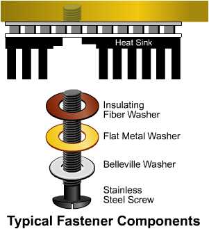
c) Mounting screws should be arranged in a symmetrical pattern relative to the module(s) so as to provide uniform pressure on the module(s) when the assembly is clamped together. To minimize heat loss through the mounting screws, it is desirable to use the smallest size screw that is practical for the mechanical system. For most applications, M3 or M3.5 (4-40 or 6-32) stainless steel screws will prove satisfactory. Alternately, nonmetallic fasteners can be used, e.g., nylon. Smaller screws may be used in conjunction with very small mechanical assemblies. Belleville spring washers or split lock-washers should be used under the head of each screw to maintain even pressure during the normal thermal expansion or contraction of system components.
d) Clean the module(s) and mounting surfaces to ensure that all burrs, dirt, etc., have been removed.
e) Coat the “hot” side of the module(s) with a thin layer (typically 0.02mm / 0.001″ or less thickness) of thermally conductive grease and place the module, hot side down, on the heat sink in the desired location. Gently push down on the module and apply a back and forth turning motion to squeeze out excess thermal grease. Continue the combined downward pressure and turning motion until a slight resistance is detected. Ferrotec America recommends and stocks American Oil and Supply (AOS) type 400 product code 52032.
f) Coat the “cold” side of the module(s) with thermal grease as specified in step (e) above. Position and place the object to be cooled in contact with the cold side of the module(s). Squeeze out the excess thermal grease as previously described.
g) Bolt the heat sink and cooled object together using the stainless steel screws and spring washers. It is important to apply uniform pressure across the mounting surfaces so that good parallelism is maintained. If significantly uneven pressure is applied, thermal performance may be reduced, or worse, the TE module(s) may be damaged. To ensure that pressure is applied uniformly, first tighten all mounting screws finger tight starting with the center screw (if any). Using a torque screwdriver, gradually tighten each screw by moving from screw to screw in a crosswise pattern and increase torque in small increments. Continue the tightening procedure until the proper torque value is reached. Typical mounting pressure ranges from 25 – 100 psi depending on the application. If a torque screwdriver is not available, the correct torque value may be approximated by using the following procedure:
In a crosswise pattern, tighten the screws until they are “snug” but not actually tight. In the same crosswise pattern, tighten each screw approximately one quarter turn until the spring action of the washer can be felt.
h) A small additional amount of thermal grease normally is squeezed out soon after the assembly is first clamped together. In order to insure that the proper screw torque is maintained, wait a minimum of one hour and recheck the torque by repeating step (g) above.
i) CAUTION: Over-tightening of the clamping screws may result in bending or bowing of either the heat sink or cold object surface especially if these components are constructed of relatively thin material. Such bowing will, at best, reduce thermal performance and in severe cases may cause physical damage to system components. Bowing may be minimized by positioning the clamping screws close to the thermoelectric module(s) and by using moderately thick materials. However, if hot and/or cold surfaces are constructed of aluminum which is less than 6mm (0.25″) thick or copper which is less than 3.3mm (0.13″) thick, it may be necessary to apply screw torque of a lower value than specified in step (g) above.
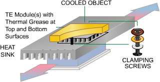
Figure (6.1)
TE Module Installation Using the Clamping Method
The proper bolt torque for TE module assemblies can be determined by the following relationship:
T=((Sa x A)/N) x K x d
where:
T = torque on each bolt
Sa = cycling 25-50 psi, static 50-75 psi.
A = total surface area of module(s)
N = number of bolts used in assembly
K = torque coefficient (use K=0.2 for steel, K=0.15 for nylon)
d = nominal bolt diameter
For steel fasteners, we typically recommend either:
6-32 d=.138 in (.350 cm)
4-40 d=.112 in (.284 cm)
The following recommended torque is calculated for nine 9500/065/018 modules held by four 4-40 steel fasteners:
T=((75 lbs/in.2 x (.44″ x .48″) x 9)/4)x 0.2 x .112 in. = 0.8 in-lbs.
6.3 Bonding with Epoxy
A second module mounting method that is useful for certain applications involves bonding the module(s) to one or both mounting surfaces using a special high thermal-conductivity epoxy adhesive. Since the coefficients of expansion of the module’s ceramics, heat sink and cooled object vary, we do not recommend bonding with epoxy for larger modules. Please consult your applications engineer for guidance. Note: Unless suitable procedures are used to prevent outgassing, epoxy bonding is not recommended if the TE cooling system is to be used in a vacuum. For module mounting with epoxy:
a) Machine or grind flat the mounting surfaces between which the TE module(s) will be located. Although surface flatness is less critical when using epoxy, it is always desirable for mounting surfaces to be as flat as possible.
b) Clean and degrease the module(s) and mounting surfaces to insure that all burrs, oil, dirt, etc., have been removed. Follow the epoxy manufacturer’s recommendations regarding proper surface preparation.
c) Coat the hot side of the module with a thin layer of the thermally conductive epoxy and place the module, hot side down, on the heat sink in the desired location. Gently push down on the module and apply a back and forth turning motion to squeeze out excess epoxy. Continue the combined downward pressure and turning motion until a slight resistance is detected.
d) Weight or clamp the module in position until the epoxy has properly cured. Consult the epoxy manufacturer’s data sheet for specific curing information. If an oven cure is specified, be sure that the maximum operating temperature of the TE module is not exceeded during the heating procedure. Note that most TE cooling modules manufactured by Ferrotec have maximum operating temperatures of 200 °C for the 95-Series.
6.4 Soldering
Thermoelectric modules that have metallized external faces may be soldered into an assembly provided that reasonable care is taken to prevent module overheating. Soldering to a rigid structural member of an assembly should be performed on one side of the module only (normally the hot side) in order to avoid excessive mechanical stress on the module. Note that with a module’s hot side soldered to a rigid body, however, a component or small electronic circuit may be soldered to the module’s cold side provided that the component or circuit is not rigidly coupled to the external structure. Good temperature control must be maintained within the soldering system in order to prevent damage to the TE module due to overheating. Our thermoelectric modules are rated for continuous operation at relatively high temperatures (150 or 200 °C) so they are suitable in most applications where soldering is desirable. Naturally these relative temperatures should not be exceeded in the process. Since the coefficients of expansion of the module ceramics, heat sink and cooled object vary, we do not recommend soldering modules larger than 15 x 15 millimeters. Soldering should not be considered in any thermal cycling application. For module mounting with solder, the following steps should be observed:
a) Machine or grind flat the mounting surface on which the module(s) will be located. Although surface flatness is not highly critical with the soldering method, it is always desirable for mounting surfaces to be as flat as possible. Obviously, the heat sink surface must be a solderable material such as copper or copper plated material.
b) Clean and degrease the heat sink surface and remove any heavy oxidation. Make sure that there are no burrs, chips, or other foreign material in the module mounting area.
c) Pre tin the heat sink surface in the module mounting area with the appropriate solder. The selected solder must have a melting point that is less than or equal to the rated maximum operating temperature of the TE device being installed. When tinning the heat sink with solder, the heat sink’s temperature should be just high enough so that the solder will melt but in no case should the temperature be raised more than the maximum value specified for the TE device.
d) Apply soldering flux to the TE module’s hot side and place the module on the pre tinned area of the heat sink. Allow the module to “float” in the solder pool and apply a back and forth turning motion on the module to facilitate solder tinning of the module surface. A tendency for the module to drag on the solder surface rather than to float is an indication that there is an insufficient amount of solder. In this event, remove the module and add more solder to the heat sink.
e) After several seconds the module surface should be tinned satisfactorily. Clamp or weight the module in the desired position, remove the heat sink from the heat source, and allow the assembly to cool. When sufficiently cooled, degrease the assembly to remove flux residue.
6.5 Mounting Pads And Other Material
There are a wide variety of products available designed to replace thermally conductive grease as an interface material. Perhaps the most common are silicon-based mounting pads. Originally for use in mounting semiconductor devices, these pads often exhibit excessive thermal resistance in thermoelectric applications. Since the pads allow for rapid production and eliminate cleanup time, they are popular in less demanding applications. Leading manufacturers in this area include The Bergquist Company and the Chomerics Division of Parker Hannifin Corporation.
Table of Contents
Do You Need More Information?
We offer more thermal solutions than the standard thermoelectric modules listed here. If you have questions, don't see the size that you need, or to place an order, contact your local Ferrotec thermal solutions representative.