13.0 Power Generation
13.1 Bismuth Telluride-based thermoelectric modules are designed primarily for cooling or combined cooling and heating applications where electrical power creates a temperature difference across the module. By using the modules “in reverse,” however, whereby a temperature differential is applied across the faces of the module, it is possible to generate electrical power. Although power output and generation efficiency are very low, useful power often may be obtained where a source of heat is available.
13.2 A thermoelectric module used for power generation has certain similarities to a conventional thermocouple. Let us look at a single thermoelectric couple with an applied temperature difference as shown in Figure (13.1)
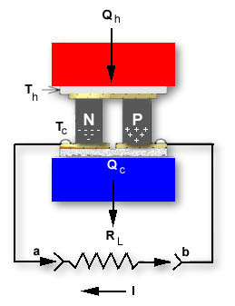
Figure (13-1)
Single Thermoelectric Couple where Th > Tc
With no load (RL not connected), the open circuit voltage as measured between points a and b is:
V = S x DT
Where:
V = the output voltage from the couple (generator) in volts
S = the average Seebeck coefficient in volts/°K
DT = the temperature difference across the couple in K where DT = Th-Tc
S = the average Seebeck coefficient in volts/°K
DT = the temperature difference across the couple in K where DT = Th-Tc
When a load is connected to the thermoelectric couple the output voltage (V) drops as a result of internal generator resistance. The current through the load is:
S x DT
____________________
RC + RLI =
Where:
I = the generator output current in amperes
Rc = the average internal resistance of the thermoelectric couple in ohms
RL = the load resistance in ohms
Rc = the average internal resistance of the thermoelectric couple in ohms
RL = the load resistance in ohms
The total heat input to the couple (Qh) is:
Qh = (S x Th x I) – (0.5 x I2 x Rc) + (Kc x DT)
Where:
Qh = the heat input in watts
Kc = the thermal conductance of the couple in watts/°K
Th = the hot side of the couple in °K
Kc = the thermal conductance of the couple in watts/°K
Th = the hot side of the couple in °K
The efficiency of the generator (Eg) is:
V x I
____________________
QhEg = We have thus far discussed an individual thermoelectric couple, but since a complete module consists of a number of couples, it is necessary to rewrite our equation for an actual module, as follows:
VO = SM x DT = I x (RM + RL)
Where:VO = the generators output in volts
SM = the module’s average Seebeck coefficient in volts/°K
RM = the module’s average resistance in ohmsIt must be remembered that module Seebeck coefficient, resistance and thermal conductance properties are temperature dependent and their values must be calculated as described in Section 11, paragraphs 11.2 through 11.2.4. The values of SM, RM, and KM must be selected at the average module temperature Tavg
Where:
Th + Tc
____________________
2Tavg = The power output (Po) from the module in watts is:
Po = RL x
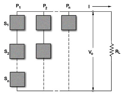
It is possible, but unlikely, that the precise conditions will exist within a given generator application whereby one module will provide the exact output power desired. As a result, most thermoelectric generators contain a number of individual modules which may be electrically connected in either series, parallel, or series/parallel arrangement. A typical generator configuration is illustrated in Figure (13.2). This generator has a NT total number of modules with NS number of modules connected in series and NP number of modules connected in parallel. The total number of modules in the system is:
NT = NS x NP
Figure (13-2)
Typical Thermoelectric Generator with a Series-Parallel Arrangement of Modules
The current (I) in amperes passing through the load resistance RL is:
NS x SM x DT I = __________________ NS x RM _____________ + RL NP The output voltage (VO) from the generator in volts is:
The Output Power (PO) from the generator in watts is:
NT x (SM x DT)2
_________________
4 x RMPO = VO x I = The total heat input (Qh) to the generator in watts is:
The efficiency (Eg) of the generator is:
PO
Eg = ——— x 100%
QhMaximum efficiency occurs when the internal resistance of the generator (RGEN) equals the load resistance (RL). The generator resistance is:
NS x RM
RGEN = —————
NP13.3 DESIGN EXAMPLE: To illustrate the typical design process let us analyze a requirement for a 12-volt, 1.5 ampere thermoelectric power generator. The generator is needed to power telemetry electronics at a remotely located oil pipeline where the hot, continuously flowing oil produces a 130 C pipe casing temperature. Flowing water (having a temperature of 10°C) also is available at the remote site, and it has been determined that an efficient water-cooled heat sink can maintain the TE generator cold-side at a temperature of +30 C. We will use the equations from Section 11 to obtain the values of SM, RM and KM for our calculations.
To begin the design process we will review the system parameters and make some preliminary calculations.
Given:Th = + 130°C = 403.2°K
Tc = + 30°C = 303.2°K
Vo = 12 volts
I = 1.5 amperesTherefor:Tav = (Th+Tc)/2 = (403.2+303.2)/2 = 353.2°K
RL = Vo/I = 12 / 1.5 = 8.0 ohms
Po = Vo x I = 12 x 1.5 = 18 watts
DT = Th-Tc = 403.2 – 303.2 = 100°KIt is usually desirable to select a relatively “high power” thermoelectric module for generator applications in order to minimize the total system cost. For this reason we will choose a 127 couple, 6-ampere module to be used in our design.
Calculating SM, RM, and KM for our selected 127-couple, 6 ampere module, the following values are obtained at Tav = 353.2°K:
SM = 0.05544 volts/°K
RM = 3.0994 ohms
KM = 0.6632 watts/°KThe required power for the load has been calculated as 18 watts. It is now necessary to determine the minimum number of modules needed to meet this load requirement. The maximum output power from one module is:
Pmax= ______________ = 2.479 watts The minimum number of modules needed is:
——
Pmax
= ——— =
2.479NTmin = 7.3 » 8 Because maximum generator efficiency occurs when RGEN = RL, it is desirable for most applications to select the series/parallel module configuration that will best approximate this resistance balance. One possible exception to the equalizing RGEN with RL is in the situation where a relatively low current (in the milliampere range) and moderate voltage is required. In this case, the connection of all modules electrically in series may give the best results. Be aware, however that the maximum output voltage from the generator will be obtained from a straight series-connected group of modules only when the resistance of the load is significantly higher than the internal resistance of the generator.
As a starting point in the evaluation of any thermoelectric power generator, it is often helpful to first examine the straight series-connected configuration. The resistance of a series string of eight modules is:
RGEN = NS x RM
————— =
NP8 x 3.0994
—————
1= 24.8 ohms It can be seen that the 24.8 ohm generator resistance is considerably higher than the 8.0 ohm load resistance, thereby indicating that a straight series module connection probably is not the best arrangement. For the all series condition where NS = 8 and NP = 1, the output voltage is:
With a group of eight modules, the next most logical connection configuration is two parallel strings of four modules, i.e., NS = 4 and NP = 2. Generator resistance for this configuration is thus:
RGEN = NS x RM
———— =
NP4 x 3.0994
————
2= 6.2 ohms While 6.2 ohm RGEN value does not exactly match the 8.0 ohm load resistance, this value normally would be considered as being within the satisfactory range. In any event, this is the closest resistance match that can be obtained with the selected module type. The voltage for this arrangement (12.49 volts) is calculated as follows:
We can now see that Vo is quite close to the desired value and it is apparent that we have obtained the optimum series/parallel configuration. If “fine tuning” of Vo is required, it will be necessary to accomplish this either by some form of electronic voltage regulation or by externally altering the applied temperature differential (DT). In certain instances it will be found that the output voltage is significantly out of range despite trying all possible series/parallel combinations. In this event it may be necessary to use an alternate thermoelectric module having a different current rating and/or number of couples.
It is now possible to complete our design analysis by determining power levels and efficiency. Since we have established Vo, output power (Po) can be simply calculated:
(Vo)2 (12.49)2
Po = ——— = ——— = 19.5 watts
RL 8.0
The total heat input (Qh) to the generator is:
The generator efficiency (Eg) is:
Eg = Po
——
Qhx 100% = 19.5
———
657.5x 100% = 2.97% The heat transferred to the cold-side heat sink (Qc) is:
Qc = Qh – Po = 657.7 – 19.5 = 638.2 watts
The maximum allowable thermal resistance (Qs) of the cold-side heat sink is :
(Qs)= Trise
————— =
Qc30°C – 10°C
—————— =
638.20.031 °C/watt For any thermoelectric generator design it is always desirable to maximize the applied temperature differential in order to minimize the total number of modules in the system. This situation can be clearly seen in Figure (13.3). Module requirements for a typical 12-volt, 1-ampere power generator are plotted at several fixed values of Th based on the use of 127-couple 6-ampere TE modules. From this graph, it is evident that a very large number of modules is needed when the cold side temperature (Tc) is high and the temperature differential, therefore, is small. Performance of the cold-side heat sink is of the utmost importance and its thermal resistance must be extremely low. In many cases, cold-side heat sink design will prove to be the most challenging engineering problem.
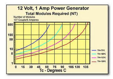
Figure (13-3)
The Total Number of 127 Couple, 6 Amp Modules Required for a 12-volt, 1 Ampere Thermoelectric Power Generator
13.4 USE OF THERMOELECTRIC MODULES IN A CALORIMETER: A lesser, yet viable, application for thermoelectric modules operating in the power generation mode is in the construction of calorimeters. The conventional calorimeter uses common thermocouples for heat measurement based solely on the Seebeck effect. Through the use of a multi-couple thermoelectric cooling module, it is possible to fabricate a calorimeter having a sensitivity (output voltage per unit of heat flux density) as much as 10 to 200 times the sensitivity of a standard copper-constantine thermocouple. When used in a calorimeter application, the thermoelectric module is often referred to as a thermopile. The open-circuit output voltage (V) of a single thermoelectric couple, as described in paragraph 13.2 and illustrated in Figure (13.1), is:
V = S x DT
Where:V = the output voltage from the couple in volts
S = the average Seebeck coefficient in volts/°K
DT = the temperature difference across the couple in °K where DT=Th-TcFor an actual TE module having a number of couples and a Seebeck coefficient of SM, the output voltage (Vo) is:
Vo = SM x DT
The heat flow through the TE or “thermopile” is:
—————
SMQ = KM x DT = Where:Q = the heat flow in watts
KM = the thermal conductance of the module in watts/°KThe total cross-sectional area (AM) of all elements in the module is:
AM = A x N
Where:AM = total area of all module elements in cm2
A = cross-sectional area of one element in cm2
N = total number of elements in the moduleThe heat flux density (q) in watts/cm2 is:
q = KM x DT
————— =
AMKM x Vo
—————
SM x AMMost standard thermoelectric cooling modules may be used in a calorimeter application but improved sensitivity may be realized by modifying the length-to-area (L/A) aspect ration of the TE elements. A relatively large L/A ratio resulting in a tall and “skinny” element will produce the best calorimeter sensitivity. To illustrate this situation let us consider the following:
The sensitivity of a module as a calorimeter (Sc) is:
Sc = Vo
—————
qSM x AM
= —————
KMIt has been seen that sensitivity (Sc) is directly proportional to the Seebeck coefficient (SM) and total cross-sectional element area (AM) and inversely proportional to the thermal conductance (KM). By rewriting the above equation in respect to thermal conductivity (k) instead of thermal conductance (KM) we have:
Sc = SM x AM
—————
k x N x A/LSince N x A = AM, the expression can be restated as:
Sc = SM x L
—————
kFrom this equation, it is evident that calorimeter sensitivity is directly related to the length (L) dimension of an element and it is desirable, therefore, to select a thermoelectric module having the largest possible element aspect ratio. Be aware that there are practical limits on element geometry due to the fragility of crystalline Bismuth telluride material. Working within these limits, however, it is possible to fabricate custom modules that are particularly suited for calorimeter use.
Table of Contents
Do You Need More Information?
We offer more thermal solutions than the standard thermoelectric modules listed here. If you have questions, don't see the size that you need, or to place an order, contact your local Ferrotec thermal solutions representative.